4 Way 2 Position Valve Diagram Dsh084btv
Valve way solenoid position working control instrumentation instrumentationtools useful applications such where cylinder element motor must final Solenoid valve valves way types functions principle manual symbols circuit read instrumentationtools different reset also How five port four way valve works air
2-Way 2-Position Valves | Pneumadyne
Position mid valve wiring diagram sponsored links Machine drawing: rotary four way valves Iso schemes of directional control valves
Valve position way control construction working
4 way manual valves • related fluid powerValve directional normally postion 5 2 valve schematicPosition valves way pneumadyne toggle high rugged combination ideal applications flow solid use.
Hydraulic directional valves lever operated hydraulics spool wegeventil hydraulik walvoil distributore schieber cassetto idraulico 4dl yuken epitome dmg hidrolik mandiriMid position valve wiring 4 way 2 position valve schematicElectrical schematics explained.
Way pneumatic position valves valve solenoid spring return normally port closed acting actuators direct cylinders automationdirect library
Thermo fluid dynamic design of a 4-way reversing valveElectronic valve function explained (to be removed) four-port three-position directional control valveValve air way port four works five.
Structure of four-way reversing valve.How five port four way air air valve works Solenoid valves types & functions instrumentation toolsSolenoid 24vdc 4v210 220v 24v.

Solenoid air valve 5 port 4 way 2 position 24vdc 4v210-08
Directional valve symbols[diagram] 3 way valve diagram 4 way valve working system heat pump air conditioner, hvac work, happyFive-port four-way valve diagram.
Machine drawing: rotary four way valvesControl direction way valves four hydraulics methods drawing actuation part 4 way 3 position control valve working & construction youtube 720pValves for pneumatic cylinders.

Way manual valve position valves hydraulic
Valves directional symbols iso control common ports positions actuation resets elements hafner pneumatik most4 way 2 position valve schematic Way four valves drawing machine rotary two variations present fivePort and position of directional control valve.
How to select electronic directional control valvesWay position valves directional symbols valve symbol two hyd shown Operator strong hen two way air valve apologize reign financial4-way reversing valves.

Enerpac hydraulic directional control valve, 10,000 psi, 4.0 gpm, 4-way
2-way 2-position valvesLever operated directional control valves – hardware & pneumatics What is a 4-way solenoid valve ? instrumentation toolsPneumatic schematics symbols explained hydraulic valve reading diagrams automationdirect solenoid schematic wiring actuated plc.
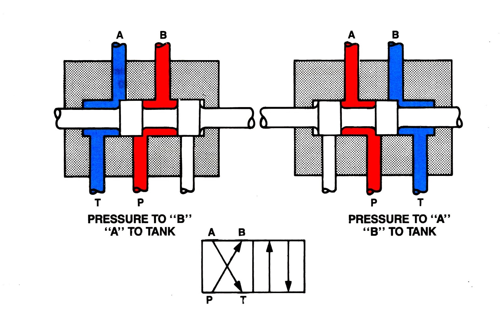
Hydraulic control directional valve way position enerpac psi grainger zoom tapValves position directional positions ports clippard Parker, 700 series, 4-way/2-position, directional control valveDsh084btv.

Valve way position electronic explained function clippard valves
Reversing way valve fluid solenoid three components slide valves thermo dynamic pilot made actually market operatedValve way air port four works five .
.


Mid Position Valve Wiring
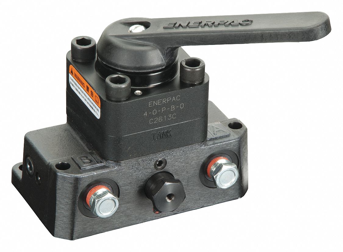
ENERPAC Hydraulic Directional Control Valve, 10,000 psi, 4.0 gpm, 4-Way

2-Way 2-Position Valves | Pneumadyne

Valves for Pneumatic Cylinders | Actuators | Library.Automationdirect.com

Port and position of directional control valve

4 Way 2 Position Valve Schematic